 Click for larger image
img00001.gif
Visual example of axial stress
FATIGUE
by Kelly
All images scanned by T. Schmierer
 Click for larger image
img00001.gif
Visual example of axial stress
 Click for larger image
img00002.gif
Visual example of torsional stress
 Click for larger image
img00003.gif
Visual example of flexural stress
 Click for larger image
img00004.gif
An S-N plot for an aluminum alloy
 Click for larger image
img00005.gif
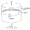
A diagram showing location of the three steps in a fatigue fracture under axial stress
 Click for larger image
img00006.gif
A diagram showing the surface of a fatigue fracture.
The rough surface indicates brittle failure, while the smooth surface represents crack propagation
 Click for larger image
img00007.gif
An example of beachmarks or "clamshell pattern" associated with stress cycles that vary in magnitude and time as in factory machinery
 Click for larger image
img00008.gif
An example of the striations found in fatigue fracture.
img00009.gif
Equation 1
img00010.gif
Equation 2
img00011.gif
Equation 3
img00012.gif
Equation 4
 Click for larger image
img00013.gif
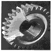
A case hardened steel gear
 Click for larger image
img00014.gif
Example of pits formed by corrosion on the surface of LiF
STRESS INTENSITY
by Kim
 Click for larger image
term811.gif
Schematic representations of
(a) an interior crack in a plate of infinite width, and
(b) an edge crack in a in a plate of semi-infinite width
 Click for larger image
term812.gif
Schematic representation showing the effect of plate thickness on fracture toughness
 Click for larger image
term83.gif
Basic modes of loading involving different crack surface displacements
 Click for larger image
term85.gif
Graph showing distribution of stresses in vicinity of crack tip
 Click for larger image
termbell.gif
Picture of the Liberty Bell
STRESS CONCENTRATION
by Noble
All images scanned by T. Schmierer
 Click for larger image
img1.jpg
Diagram showing
(a)The geometry of surface and internal cracks.
(b) Schematic stress profile along the line X-X' in (a),
demonstrating stress amplification at crack tip positions
img2.gif
Equation 1
img3.gif
Equation 2
 Click for larger image
img4.jpg
Diagrams showing stress concentration factor plots for three different macroscopic flaw situations
ENERGY METHODS
by Yue
All images scanned by M. Gallagher
 Click for larger image
img00001.jpg
Diagram of a plate with a crack growing with an applied stress
 Click for larger image
img00002.jpg
Fractograph of ductile cast iron showing a transgranular fracture surface
 Click for larger image
img00003.jpg
Fractograph of an intergranular fracture surface
 Click for larger image
img00004.jpg
Three modes of crack surface displacements
 Click for larger image
img00005.jpg
A cracked body with a force (F) and (a) is the crack length
 Click for larger image
img00006.jpg
A graph of the increase of growth rate with crack size
 Click for larger image
img00007.jpg
Illustration of Charpy and Izod Impact Tests
 Click for larger image
img00008.jpg
A graph of the temperature dependence on the Charpy V-notch impact energy
(curve A) and percent shear fracture (curve B)
NUMERICAL
THEORY
by Midkiff
All images scanned by J. Midkiff
 Click for larger image
midkiff1.jpg
Structure of a three-member truss
 Click for larger image
midkiff2.jpg
Single truss member
midkiff3.jpg
Equation 1
midkiff4.jpg
Equation 2
 Click for larger image
midkiff5.jpg
Force diagram of single truss member
midkiff6.jpg
Equation 3
midkiff7.jpg
Equation 4
midkiff8.jpg
Equation 5
 Click for larger image
midkiff9.jpg
Three member truss
 Click for larger image
midkif10.jpg
diagram showing displacements and external forces
on a three member truss
midkif11.jpg
Equation 6
midkif12.jpg
Equation 7
midkif13.jpg
Equation 8
 Click for larger image
midkif14.jpg
Nodal forces on a three member truss
midkif15.jpg
Equation 9
midkif16.jpg
Equation 10
midkif17.jpg
Equation 11
EXAMPLES
by Schultz
All images preprocessed in Patran and processed in
Abaqus by J. Schultz on an ESM workstation
 Click for larger image
rmin.gif
FEA results of stresses in a plate with an elliptical crack
 Click for larger image
rmed.gif
FEA results of stresses in a plate with an elliptical crack
 Click for larger image
circle.gif
FEA results of stresses in a plate with a circular crack
 Click for larger image
mesh.gif
Mesh with boundary conditions for one of the models
 Click for larger image
GEOM.gif
Geometry of FEA drawn in Autocad
SIMPLE COMPUTER PROBLEM
by Tingler
All images scanned by T. Schmierer
Tingler8-1.jpg
Equation 8.1
Tingler8-2.jpg
Equation 8.2
Tingler8-5.jpg
Equation 8.5 a,b,c
Tingler8-6.jpg
Equation 8.6
Tingler8-7.jpg
Equation 8.7
Tingler8-8.jpg
Equation 8.8
Tingler8-9.jpg
Equation 8.9
Tingler8-10.jpg
Equation 8.10
HISTORY/INTRODUCTION
by Widas
 Click for larger image
widas1.jpg
Figure 1 from http://www.noraneng.com
 Click for larger image
widas2.jpg
Mesh diagram of a van
 Click for larger image
widas3.jpg
Figure 3 from http://umass.edu/mie/labs/mda/fea/fealib/goldstein/PROJECT.html
 Click for larger image
widas4.jpg
Non-linear model of a bicycle frame
 Click for larger image
widas5.jpg
Fatigue analysis of a train
EXPERIMENTAL
DUCTILE FRACTURE
by Bailey
All images scanned by T. Schmierer
 Click for larger image
bailey1.jpg
A tensile stess-strain curve
 Click for larger image
bailey2.jpg
A scanning electron fractograph of ductile cast iron, examining a transgranular fracture surface
 Click for larger image
bailey3.jpg
Figure showing the macroscopic differences between two ductile specimens(a,b)
and the brittle specimen (c)
 Click for larger image
bailey4.jpg
Figure demonstrating the microscopic qualities of ductile fracture surfaces
 Click for larger image
bailey5.jpg
Figure demonstrating the microscopic qualities of ductile fracture surfaces
 Click for larger image
bailey6.jpg
Sheared aluminium specimen showing cup and cone, and brittle fracture
 Click for larger image
bailey7.jpg
Graph that determines brittle to ductile transition
through an impact test for a 1018 hot-rolled steel
BRITTLE FRACTURE
by Ballard
 Click for larger image
chevrons.gif
Chevron fracture surface
 Click for larger image
intergran.gif
Diagram showing intergranular fracture
 Click for larger image
radiate.gif
Radiating ridge fracture surface
 Click for larger image
transgran.gif
Diagram showing transgranular fracture
DESIGN
by Gordon
All images scanned by T. Schmierer
 Click for larger image
cf-1.gif
Graph showing aluminum oxide's modulus of elasticity as a function of porosity
 Click for larger image
cf-2.gif
Graph showingaluminum oxide's modulus of rupture as a function of porosity
 Click for larger image
cf-3.gif
Diagram of a ceramic material before sintering
 Click for larger image
cf-4.gif
Diagram of a ceramic material during sintering
 Click for larger image
cf-5.gif
Diagram of a ceramic material after sintering
pe-1.jpg
Equation showing the minimum fiber length for a continuous fiber composite
pe-2.jpg
Equation showing the tensile strength of a discontinous
fiber composite with fiber length greater than lc
pe-3.jpg
Equation showing the tensile strength of a discontinous
fiber composite with fiber length less than lc
 Click for larger image
rf-1.gif
Figure showing the tenile and compressive stress on tempered glass
se-1.jpg
Equation for factor of safety
 Click for larger image
sf-1.gif
A poor design that will create a stree concentration
 Click for larger image
sf-2.gif
A good design that will minimise stress concentration
te-1.jpg
Equation for the minimum thickness of material before plane strain behavior occurs
te-2.jpg
Equation for the fracture toughness of a material with a thickness less than B
te-3.jpg
Equation for the fracture toughness of a material with a thickness equal to or greater than B;
when it fractures in mode I
te-4.jpg
Equation for the critical applied stress required to cause failure in a material
te-5.jpg
Equation for the critical crack length required to cause failure in a material
 Click for larger image
tf-2.gif
Diagram of a mode I fracture
 Click for larger image
tf-3.gif
Diagram of a mode II fracture
 Click for larger image
tf-4.gif
Diagram of a mode III fracture
 Click for larger image
pg-1.gif
Graph showing composite performance in relation to stress alignment
FRACTOGRAPHY
by Halahan and Mutter
 Click for larger image
clev1.jpg
Stainless steel showing transgranular cleavage
Scanned by M. Gallagher
 Click for larger image
clev2.jpg
TiB2 showing cleavage
Scanned by M. Gallager
 Click for larger image
clev3.jpg
Ni base alloy showing cleavage
Scanned by M. Gallagher
 Click for larger image
clev4.jpg
Silicon carbide showing small cleavage
Scanned by M. Gallagher
 Click for larger image
cohesive1.jpg
Obvious decohesion
Scanned by R. Halahan
 Click for larger image
cohesive2.jpg
Stainless steel showing hydrogen embrittlement
Scanned by R. Halahan
 Click for larger image
cohesive3.jpg
Stainless steel showing decohesive rupture
Scanned by M. Gallagher
 Click for larger image
cohesive4.jpg
Carbon-Magnesium steel showing stress corrosion cracking
Scanned by M. Gallagher
 Click for larger image
cohesive5.jpg
Low carbon steel with a layer of oxide
Scanned by R. Halahan
 Click for larger image
cohesive6.jpg
Gray cast iron with sulfate deposites
Scanned by R. Halahan
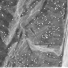 Click for larger image
fatig1.jpg
Nickel based alloy with fatigue striations
Scanned by M. Gallagher
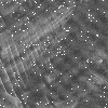 Click for larger image
fatig2.jpg
Enlarged picture of fatig1.jpg
Scanned by M. Gallagher
 Click for larger image
fatig3.jpg
Nickel based alloy with jagged fatigue striations
Scanned by M. Gallagher
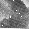 Click for larger image
fatig4.jpg
Titanium alloy with fatigue striations
Scanned by M. Gallagher
 Click for larger image
void1.jpg
High carbon steel with an elongated dimple
Scanned by M. Gallagher
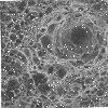 Click for larger image
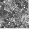
void2.jpg
AISI 10B21 Steel with well defined microvoid coalescence
Scanned by M. Gallagher
 Click for larger image
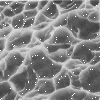
void3.jpg
Aluminum alloy with microvoids
Scanned by M. Gallagher
 Click for larger image
void4.jpg
Titanium alloy with equiaxed and elongated dimples
Scanned by M. Gallagher
 Click for larger image
void5.jpg
Nitralloy 135 M with microvoid coalescence
Scanned by M. Gallagher
FRACTURE TOUGHNESS
by McMurtry
 Click for larger image
fig1.jpg
A specimen with an internal crack
 Click for larger image
fig2.jpg
A specimen with a through-thickness crack
 Click for larger image
fig3.jpg
A specimen with a half circle surface crack
 Click for larger image
fig4.jpg
A fracture toughness vs. thickness graph
 Click for larger image
fig5.jpg
Three modes of crack surface displacement
 Click for larger image
fig6.jpg
Two ASTM standard compact specimen of different b sizes
 Click for larger image
fig7.jpg
Graph of fracture toughness vs. temperature for different steels
 Click for larger image
fig8.jpg
A graph of fracture toughness vs. temperature for various strain rates
applied to A572 steel
EXPERIMENTAL FATIGUE
by Meyer
All images scanned by C. Meyer
 Click for larger image
IMG00001.GIF
Fracture appearances of fatigue failures in bending
 Click for larger image
IMG00002.GIF
Typical fatigue zone with identifying marks
 Click for larger image
IMG00003.GIF
Graph showing the effect of hardness on the fatigue life
of threads rolled before and after heat treatment
 Click for larger image
IMG00004.GIF
Graph of bending fatigue test results on sections from crankshafts:
endurance limit versus surface treatment
 Click for larger image
IMG00005.GIF
Typical fatigue life curve
 Click for larger image
IMG00006.GIF
Bending angle guide
 Click for larger image
IMG00007.GIF
Graph of experimental data: angle vs. cycles to failure
 Click for larger image
IMG00008.GIF
Graph of crack growth rates obtained from adjacent pairs of a vs. N data points
 Click for larger image
IMG00009.GIF
figure showing completely reversed controlled strain test and
two possible stress responses, namely cycle-dependent
hardening and softening
 Click for larger image
IMG00010.GIF
Diagram of a stable stress-strain hysteresis loop
 Click for larger image
IMG00011.GIF
Elastic, plastic, and total strain vs. Life curves
 Click for larger image
IMG00012.GIF
A tension fatigue failure of a helicopter rotor blade flapping link
MOVIES
by Luszcz and Mix
cyclic.mpg and cyclic2.mpg
Fracture of a Hercules Graphite fiber/vinyl ester matrix composite resulting from a completely reversed load
controlled fatigue test
(performed by Nikhil Verghese - Tech graduate student)
brittle.mpg
shows brittle fracture of a class 20 gray iron sample
resulting from a constant strain tensile test (performed by J. Luszcz and J. Mix)
ductile.mpg
shows ductile fracture of a 4 wt% Cu in Al sample resulting
from a constant strain tensile test (performed by J. Luszcz and J. Mix)
fractures.jpg
shows resulting fractures of gray iron (brittle fracture,
round specimen), 4 wt% Cu in Al (ductile fracture, flat specimen), and
polyethylene (extremely ductile fracture, white specimen) (taken by J. Luszcz and J. Mix)